The principle of the action of a magnetic barrier separator intended for the enrichment of granular weakly magnetic ores is described. The results of laboratory studies of the enrichment of mineral sands, as well as industrial tests of an experimental barrier separator at the Volnogorsk State Mining and Metallurgical Combine (VGGMK) are presented. High efficiency and reliability of its operation are shown.
Introduction
High-intensity magnetic separation of low-magnetic ores on roller and rotor separators includes the attraction of magnetic grains to the protrusions of the rolls or ferromagnetic plates and the continuous removal of the attracted particles from the strong magnetic field for their subsequent discharge into the magnetic product. To ensure this removal, the separators are equipped with complex and expensive rolls and rotors, drives and bearings.
The utilization factor of the magnetic system of such separators is low, since a significant part of the space between the poles is used only for transporting the magnetic product from its attraction zone to the discharge zone. A significant part of the power consumed by the separator is not spent on extraction
magnetic product, and on the rotation of the rolls and rotors. For example, the drive power of the rolls is 60 70% of the total power consumption 1. The price of these rotating devices, drives and bearings reaches 50% or more of the total price of the separator. In the case of a roller separator, the enriched material moves in a narrow gap
between the surface of the pole piece and the roll, which rotates at high speed. This leads to rapid abrasive wear of the protrusions of the rolls with granular material. As a result, the profile of the protrusions changes, which leads to a decrease in the extraction of magnetic particles.
Design and principle of operation of the barrier separator
These disadvantages are absent in the separator, which implements the method of barrier magnetic separation. Numerous laboratory studies have confirmed the high efficiency of the new method 2.3.
The separator consists of a magnetic system and a series of inclined channels located in the gap between the poles. The walls, bottom and ceiling of each channel have smooth surfaces. There are no mechanical obstacles to the movement along the channel of grains of the enriched material.
Due to the special structure of the walls, a magnetic field gradient is created, directed from the bottom up perpendicular to the direction of flow of the separated material moving inside the channel. The region where the product of magnetic induction by its gradient is the largest is located above the bottom and extends over the entire length of the channel. This is the area of the magnetic barrier.
The material to be enriched is fed into the channel above the region of the magnetic barrier along its strike. Non-magnetic grains pass through the magnetic barrier to the bottom of the channel and slide down it into the receiver of a non-magnetic product. Magnetic grains cannot penetrate the magnetic barrier and are not attracted to the channel walls.
Therefore, they slide down over the magnetic barrier into the receiver for the magnetic product. Thus, due to the magnetic barrier, the stream of enriched material is divided into flows of magnetic and non-magnetic particles.
 In fig. Figure 1 shows, as an example, the distribution of magnetic induction B (curve 1) in the vertical plane of the longitudinal symmetry of the channel. The highest value of induction (0.83 T) is achieved at the canal ceiling. An increase in induction from the bottom to the top of the channel leads to the appearance of an induction gradient (grB). The product of the induction and the induction gradient BgrB (curve 2) is an extremal function. The extremum region of this function is the region of the aforementioned magnetic barrier.
In our example, BgrB = 12.6 T2 / m. Therefore, if a magnetic grain has a specific magnetic susceptibility = 20010-8 m3 / kg, then even with such a small magnetic field induction (0.83 T) it will be held in air by a specific magnetic force of 20 m / s2, i.e. two forces of gravity.
Magnetic grains always have a certain range of magnetic susceptibility. Therefore, under the influence of magnetic force, they are dispersed along the height of the channel above the magnetic barrier. Grains, whose magnetic susceptibility is greater, move along the magnetic barrier in the upper layers of the flow of the enriched material. However, they do not rely on underlying grains. All grains are floating in the air independently of each other, since they are supported by magnetic forces. Grains, colliding with each other, exchange energy, as is the case in a turbulent fluid flow. This analogy is further enhanced by the fact that the grain flow does not have laminar viscosity, but has turbulent viscosity as a result of the collision of grains with each other.
Non-magnetic grains begin to move down under the action of gravity immediately after the enriched material enters the channel. This movement occurs inside a stream of magnetic grains suspended in air.
Laboratory research
All previously conducted laboratory studies of the barrier separation of mineral sands and manganese ores have shown high efficiency of this process. However, it was found that grains with increased magnetic susceptibility are gradually attracted to the walls of the channel and gradually accumulate in it. To study the possibility of eliminating this phenomenon, experiments were carried out in which the enriched material was subjected to preliminary separation in a scalping mode, i.e. with induction of 0.2 T. The weight yield of the resulting magnetic product was 0.7 1.5%.
Laboratory studies using the scalping regime were performed on the conductive fraction of the mineral sands of the Volnogorsk mining and processing plant. The conductor fraction was a mixture of magnetic ilmenite and non-magnetic rutile. In industrial conditions, this conductive fraction is enriched in a roller separator.
The laboratory separator on which the studies were conducted had one channel inclined at an angle of 300 to the vertical. In all experiments, grains with increased magnetic susceptibility were removed from the samples in a scalping mode. The material thus prepared was then subjected to two methods of barrier magnetic separation. The non-magnetic product of the first admission was refined in the second admission of separation.
The research results are shown in Table 1.
Table 1. Results of dry separation of the conductive fraction of mineral sands (rutile and ilmenite)
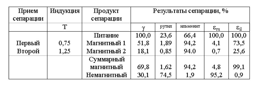
– mass yield of separation products, rutile, ilmenite – the content of rutile and ilmenite in the separation products, ru and il – extraction of rutile and ilmenite in the separation products.
From the above data it follows that low loss of expensive non-magnetic rutile in the magnetic product was obtained at the laboratory barrier separator. Its content in ilmenite concentrate is only 1.62% compared with 3 4% in ilmenite concentrate of roller separators operating at the VGGMK concentrator.
The extraction of ilmenite in a magnetic product is more by 6%, and its content in a magnetic product is 1% more than in a magnetic product of roller separators.
The positive laboratory results obtained allowed us to begin the development and manufacture of an experimental barrier magnetic separator.
During research, the magnetic product did not accumulate in the channels.
Industrial testing of an experimental barrier magnetic separator
The process of barrier separation is carried out in inclined matrices 1 (Fig. 2), each of which consists of a number of channels described above. The matrices are located between the pole pieces 2 and the horizontal closing magnetic cores 3 (Fig. 3 and 4) of the magnetic system. Each has a width of 0.5 m. The matrix has 25 channels. The width of each channel is 10 mm and the length is 220 mm.
Above the matrices are scalping rollers 4, designed to remove grains with increased magnetic susceptibility. Rollers with a diameter of 0.1 m have protrusions and depressions on their surface.
The magnetic field in the matrices is created by electromagnetic coils 5. The maximum value of induction in the matrices is 1.2 T.
A magnetic field is supplied to the scalping roller through a ferromagnetic plate 6, creating an induction of 0.3 T in the separation zone.
The material to be enriched from the feeder 7 is fed into the gap between the scalping roller and the plate 6. A stream of 8 particles with increased magnetic susceptibility is sent to the magnetic product. The rest of the material is sent to the matrix channels for barrier separation. Any of the resulting products, magnetic 9 or non-magnetic 10, can be sent for subsequent cleaning to the next method of barrier separation. In our example, a non-magnetic product of the first separation technique is sent for cleaning through groove 11 (Fig. 3).
The picture of the fluxes of magnetic particles upon their exit from the channels is shown in Fig. 4. Two streams flow from each channel. Each stream under the action of the horizontal component of the magnetic force is pressed against the wall of the dividing partition 12 separating the channels.
Tests of the experimental barrier separator were carried out at the VGGMK concentrator. The conductor fraction of the gravity concentrate of mineral sands was enriched. The enrichment of this fraction at VGGMK is carried out using induction roller separators 2EVS of various modifications. The average technological performance of these separators are shown in table 2.
The data presented indicate that during the operation of 2EVS separators in an industrial environment there is a significant mutual clogging of enrichment products. The content of expensive non-magnetic rutile in the magnetic product reaches 4%, and the content of ilmenite in the rutile product is 5%. Performance is given for first-time meals.
Table 2. Average technological performance indicators of induction roller separators 2EVS

The tests of the experimental barrier separator were carried out simultaneously with the tests of the 2EVS-36/100 serial separator, which was specially adjusted for this purpose. Technological test results are shown in table 3.
Table 3. Technological results of comparative tests of an experimental barrier separator for induction roller separator 2EVS-36/100

The data presented indicate that the technological performance of the barrier separator is better than the performance of one specially adjusted serial separator 2EVS-36/100, if they have approximately the same specific productivity with separators operating at the plant. The rutile content in the magnetic product of the barrier separator is 0.82%, that is, two times less than in the magnetic product of the roller separator. The barrier separator also has a higher ilmenite content in the magnetic product with a higher extraction of ilmenite.
With an increase in the specific productivity of the barrier separator by 1.5 times, that is, up to 3 t / (hm), the content of rutile in the magnetic product increases to 3%, but in other indicators it still exceeds not only the average performance of 2EVS in the plant , but also the performance of the reference sample separator.
Over the entire test period, the accumulation of a magnetic product in the separator channels was not observed. The economic effect of using the separator is 65335 hryvnia per year. Savings are achieved by reducing energy consumption, maintenance costs and the purchase of spare parts.
The calculation was made at standard costs, although actual costs at enterprises are higher than standard. Thus, monetary savings over 3.5 years will be equal to the price of one roll separator.
Conclusion
Comparative tests showed that the barrier separator can effectively enrich the mineral sands, reliable and easy to maintain. Moreover, compared with the roller separator, up to 60% of energy is saved, there are no costs for maintenance and repair of drives and bearings.
Sources of information
● Turkenich A. M. A continuous barrier magnetic separator for the treatment
of weakly magnetic ores // Magnetic and Electrical Separation. – 2001. –
Vol. 10 (4). – pp. 209 – 211.
● Turkenich A. M. Dry barrier separation of rutile and ilmenite on a laboratory separator “MAG-ELECTRO” // Zagagachenya cinnamon
kopalin. Na-Uk-tech. zb. – 2000.- No. 9 (50) .- P.37-41.
● Turkenich A.M. Barrier magnetic separation of manganese ore into
Hydro-Mag laboratory separator // Cinnamon
kopalin. Science. zb. – 2001.- No. 10 (51) .- P.39 – 43.
AUTHOR: TURKENICH A.M., Dr. tech. of sciences
© 2007 MHT